A
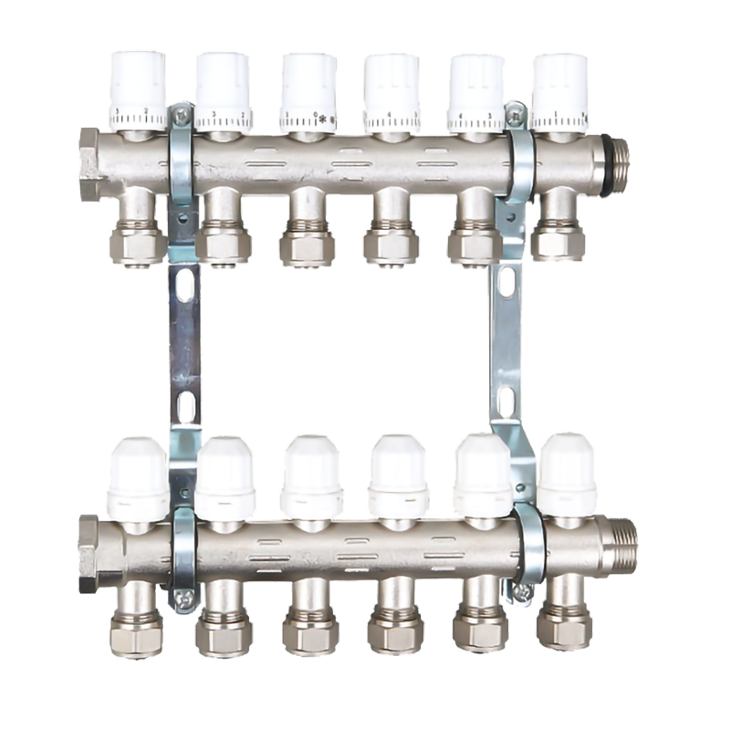
UFH Manifold Valve is the central control hub for your underfloor heating system, and they’re responsible for managing water flow rates and any room zoning that you have. They circulate heated water around the pipes and provide each zone with comfortable, energy-efficient heating.
An Underfloor Heating Manifold is an essential part of any hydronic underfloor heating system and consists of a flow bar (with two-port valves) and return bar with circuit valves mounted with actuators, and a pump that moves the water to each of the pipe loops connected to each manifold rail. These valves are controlled by a thermostat to open and close, allowing the water to flow into each pipe loop and heat the room as required.
Once the water has been pumped into each loop, it’s mixed with warmer water from the primary circuit via the mixing unit which controls the temperature of the incoming water. This allows the system to balance and distribute the water in each circuit to achieve a constant temperature throughout the system – this is crucial to ensure efficient heating.
The primary circuit of the manifold connects to the heat source - either a boiler or heat pump - and regulates incoming water by sending it through the Mixing Unit, which allocates it to each of the floor circuits to achieve an ideal, consistent water temperature in each zone. Once the circulating and blending process has been completed, the heated water is returned to the manifold’s flow bar, where it is then sent back through the return manifold to the radiators or other heat sources installed in the room.
Manifolds can contain a number of varying loops and are available in different sizes and configurations, depending on the size of the underfloor heating system and whether it has multiple zones or not. They also come with a range of temperature gauges and pre-set flow meters which allow you to achieve the correct hydronic balance in your underfloor heating system.
Underfloor Heating Manifolds should be placed in the central position to each heating zone for maximum performance, as this ensures that the minimum length of pipes can be used for each individual zone, and helps ensure that the water is always at the same temperature. You’ll also want to take into account the design of each zone - it should be sized correctly, taking into account factors such as heat losses, floor construction and heat outputs, as this will affect how much heat the system needs to deliver.

Material: The main raw material of the copper pipe connector is HPb58-2 bar material, and the specification range is Ф16~Ф100 to produce different types of products. The metal content of the material ratio is as follows: Cu 57~61% Pb0.8~2.5% Zn36~40%, impurity content range: Sn, P, Mn, Fe, Ni, Mg, As, Sb, Al, S total not allowed to exceed 2% is recognized by the non-ferrous industry as the best raw material for the manufacture of various valves, pipe connections, precision instruments, and watch parts.
Application range: It is widely used in the pipeline system of cold, hot water, acid, alkali, salt and other liquids and gas, oxygen, compressed air and other media.


